Phased-Array Radar System
Circuit Design & Schematic
The phased-array radar system is composed of one transmitter and two seperate reciever channels to resolve the angle of reflection. The transmitter is build around the Analog Devices ADF4158 chip set to generate frequency chirps for the FMCW detection scheme. The reciever uses a dual active mixer (ADL5802) to downconvert the reflected signal and uses an IF filter to compensate for the range dependend attenuation of the reflected signals. To process the radar signals, a dual high-speed ADC (LTC2292) feeds the digitized signal into an digital signal processor from Analog Deivces (ADSP-BF531) with external SRAM. The board can either be accesed by USB or for high-speed communication via an Ethernet interface. An ultra-stable oven quarz provides the reference clock signal for all components.
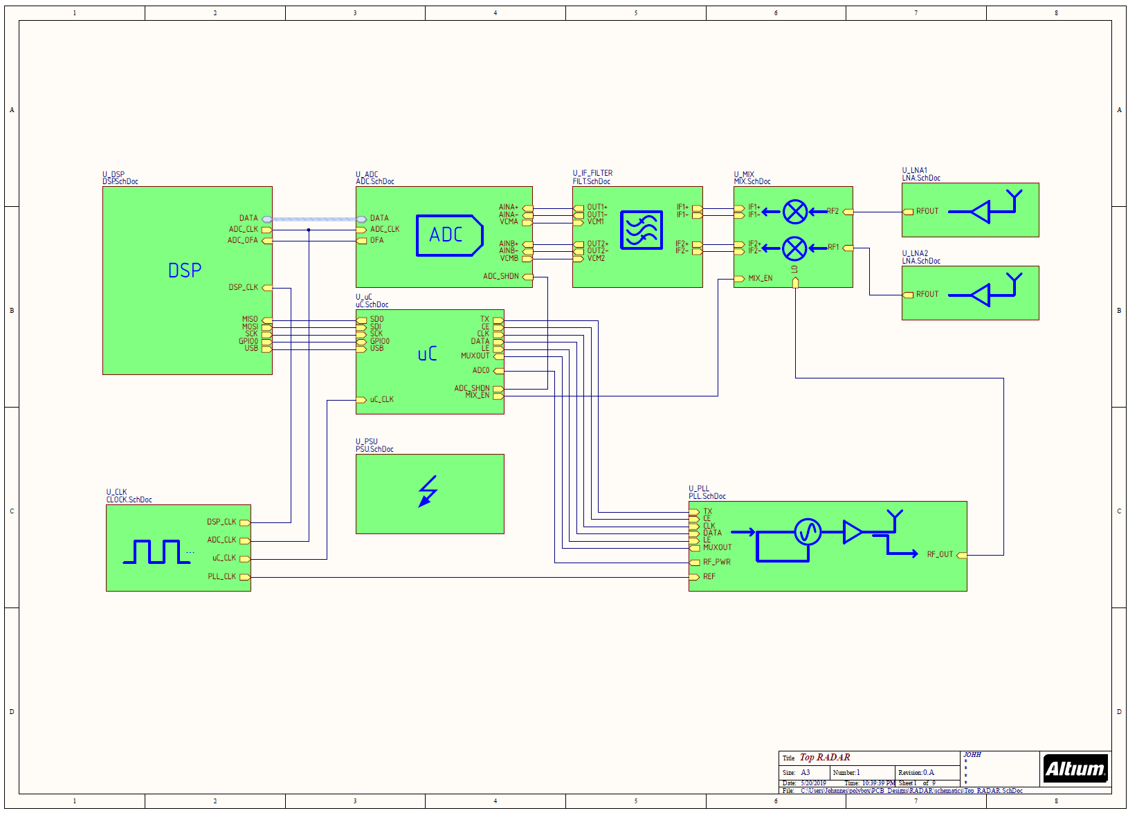
Schematic. Click for PDF.
Board Layout & Manufacturing
The layout is deployed on a 6-layer PCB stackup with Rogers RO4350 substrate between the two outermost layers. The board has been assembeled with an homemade reflow-oven and also features two RF-shields to minimze crosstalk between the reciever and transmitter part of the circuit, see Fig. 2.
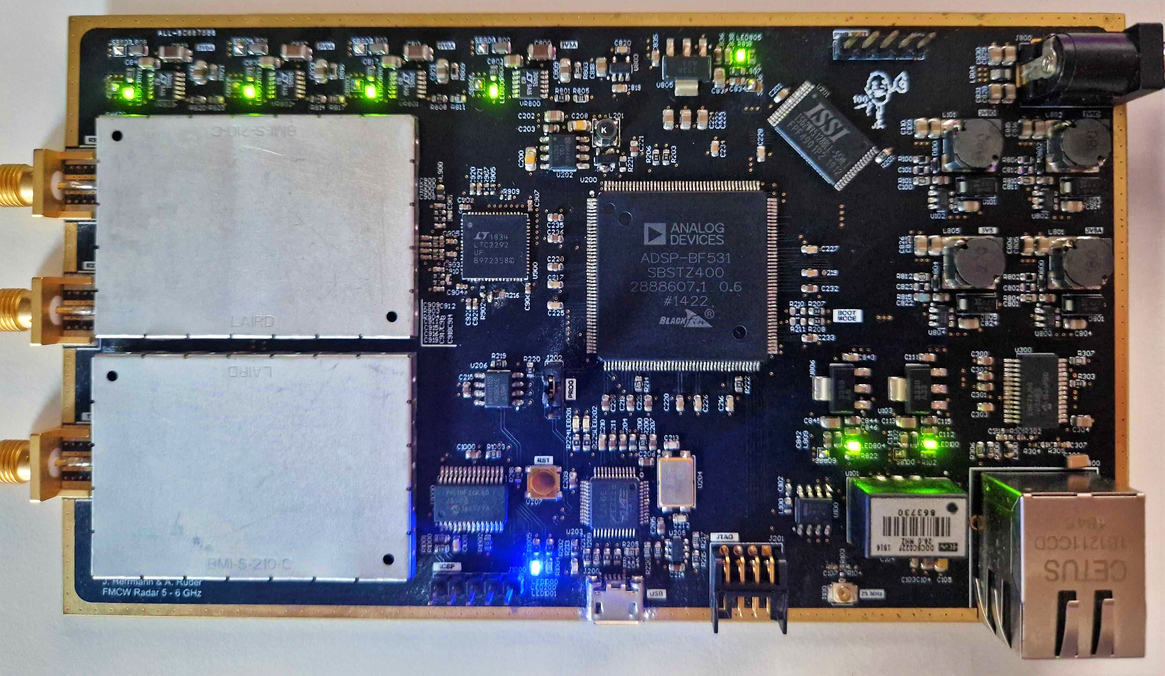
Fig. 1. - Picture of the assembled board.
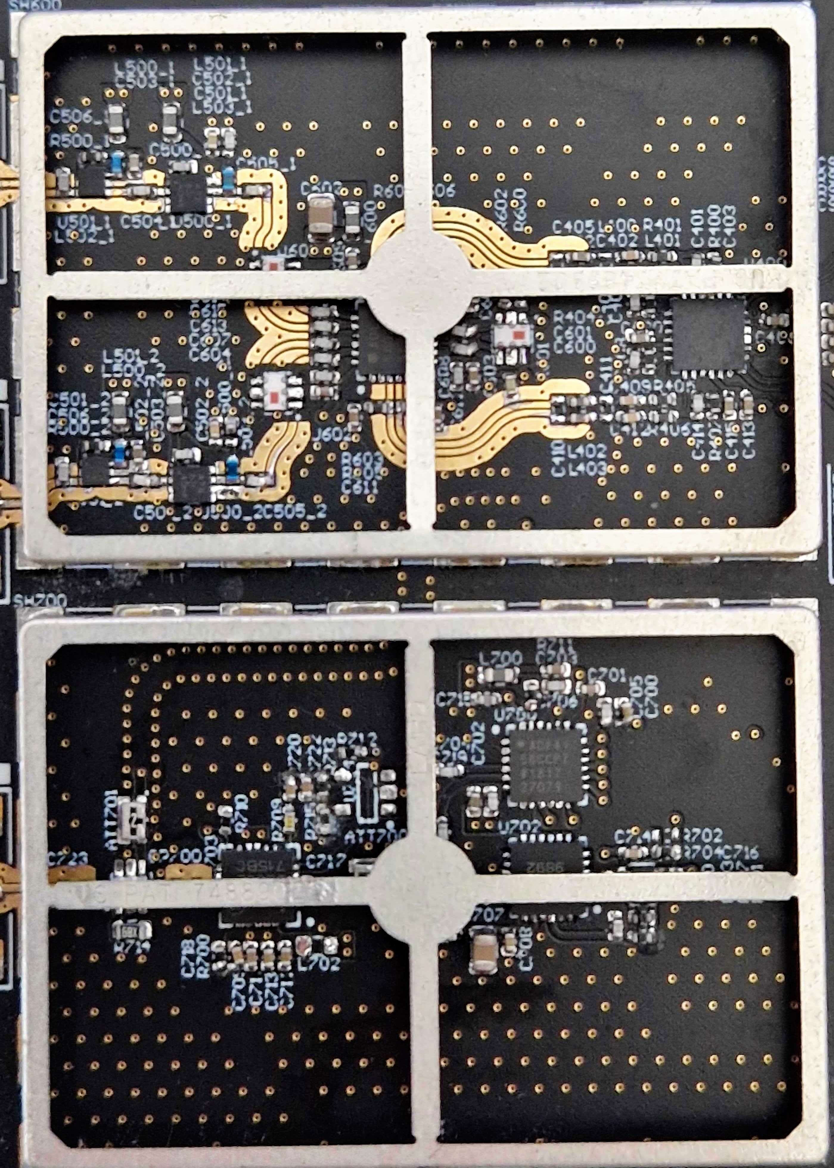
Fig. 2. - Picture of the reciever (top) and transmitter (bottom) without shield.